K2 Designer for Visual Studio - Design Canvas
The K2 Design Canvas is a visual design environment where you can drag and drop elements to build your workflow process. Most elements are configured by means of stepping through wizards, which contain the settings necessary to complete the step. There are two views with the design canvas: the Workflow View and the Document View.
Workflow View
The Workflow View is the primary view when working within the K2 Designer for Visual Studio environment. Activities and events found in the toolbox are dragged, then dropped, onto the canvas to build the workflow.
For a list of workflow design patterns, see the quick reference sheet K2 Studio Wizards.
Document View
The Document View provides a place for you to document your process. This canvas can be used to add relevant documentation and notes. The information contained in the Document View may be exported as a rich text file.

The K2 for Visual Studio design canvas menu is a context menu and can be accessed by right clicking on an open area of the design canvas.
Output Window
The Output window is the standard Visual Studio Output window that displays relevant information when building workflows and compiling projects. The output window is typically visible in the lower portion of the Visual Studio IDE.
Use the View menu to turn the uutput window on or off within the environment. In order to view more detailed build information set the output window to use verbose mode.
Error List
The Error list displays any errors that occur when building or deploying K2 projects. The Error list is also visible in the lower portion of the Visual Studio IDE, similar to the default position of the output window.
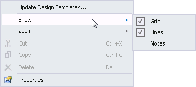
The Show menu enables you to configure the look and feel of the design canvas:
| Feature | What it is |
|---|---|
| Grid | The Grid is a matrix of dots that enable the default activities to align to the canvas |
| Lines | When selected, the lines display in their selected color. When disabled, the lines are visible but shaded in a lighter color |
| Notes | Notation can be added to the process |
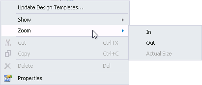
The Zoom menu changes the visual scale of the canvas. This feature allows you to increase the visual area of the canvas. This is useful for when there are a high number of elements in a process. Changing the scale of the canvas allows you to view the whole canvas or the entire process.
| Zoom Menu | |
|---|---|
| In | Increases the scale of the canvas |
| Out | Decreases the scale of the canvas |
| Actual Size | Changes the scale of the canvas to the default size |
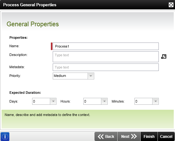
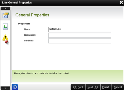
The General Properties Wizard captures and maintains the details pertaining to the Process.
| Feature | What it is | How to use it |
|---|---|---|
| Name | Defines the name of the process | The name uniquely identifies the process within the context of the project. |
| Description | Describes the process in native language | Use this field to provide a description as to what the process accomplishes in the context of the project. |
| Metadata | The metadata describes the data content of the project | Add metadata that defines the process. |
| Priority | Prioritize the process | The priority level set on the process will appear in K2 Workspace visually identifying the process's priority level. |
| Expected Duration | Captures the time allocated to an instance of the process | The expected duration sets a maximum time allowed for the process to complete. This enables the process execution time and actions required to be monitored to ensure that the process instance is actioned and or completed. |
The design canvas is customizable using the canvas context menu. The menu can be accessed from the top right of the canvas or by right clicking on the design canvas.
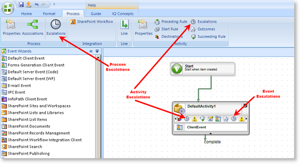
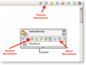
Escalation Definition: The process of handling the outcome of a process, activity or event item instance where the designated destination user has not actioned the item within a specific, allocated period. The escalation principle applies to a process and an activity since an activity that is not completed will prevent an entire process from not completing. Escalations can be configured at process and activity level. See the topics listed below to configure one of these features.
Escalations must be configured manually. When an Escalation is not configured, the process, activity or event will remain unmonitored if the destination user does not action it and consequently complete the process.
Levels of Escalations
The Escalation Rule can be exercised at the following levels in a process.
| Escalation Levels | |
|---|---|
| Process Level | The process will escalate based on the conditions configured at process level |
| Activity Level | The process escalates when the activity is not actioned before the escalation takes place. |
| Event Level | The Event level escalation escalates only the event within the activity. Where multiple events exist within a single activity, one or more events can be expired. For Event Level: When the event is expired by the escalation, the activity continues to exist until it is completed or is expired by an escalation. |
The Escalation Wizard
The Escalation Wizard enables you to use escalation templates to configure the escalation. The action template is a defined course of action performed when the escalation occurs. Two core items are configured during this process, namely the 1) Escalation Rule, 2) Action Template.
Escalation Rule
The Escalation Rule forms the basis of the Escalation Wizard and determines how the escalation takes effect. The Action Template is configured after the Escalation Rule has been determined.
| Escalation Rule |
Process |
Default Activity |
Event Item |
|---|---|---|---|
| Escalate On |
|
|
|
| Escalate After |
|
|
|

Action Templates
The table below provides a summary of the Action Templates' availability at the various levels with the K2 Designer.
The Action Template is a system feature that enables the developer to configure the escalation to either escalate or do more; take action when the escalation takes place.
| Escalation Action Templates |
Process |
Default Activity |
Event Item |
|---|---|---|---|
| Default |
|
|
|
|
|
|
|
|
| Expire Activity |
|
|
|
| Goto Activity |
|
|
|
| Redirect |
|
|
|
K2 provides exception management within a process. If required, exceptions can be incorporated within the process start and finish rules, or created for line rules and activities.
The Exception Rule is identified by the  icon.
icon.
Locating the Exception Rule
The exception icon can be found in the following locations:
Process Title Bar
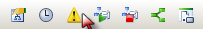
Design Canvas - Right Click
Activity Strip
Activity Property Bar
Line Rule Bar
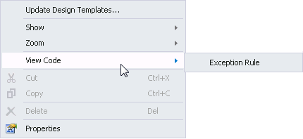
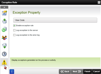
Exception Rule Options
There are three main configuration options available for exceptions:
| Option | What it is | How to use it |
|---|---|---|
| Enable exception rule | Enabling this option allows the designer to add custom exception code to the process, line or activity | Click on the check box, then click on the View Code button to load the exception code editing screen. Insert the required exception code within the process exception class (see below) |
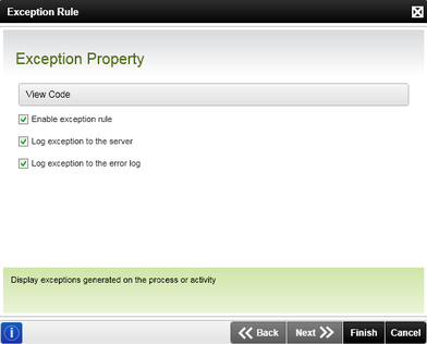
| Log exception to the server | Enabling this option adds the execution of an exception to the K2 server log | Click on the check box |
| Log exception to the error log | Enabling this option adds the execution of an exception to the error log | Click on the check box |
Log exception to the server: The HostServerErrorLog can be found in the Bin of the K2HostServer.
Log exception to the error log: The Error Log can be found in the following location in Workspace, Server>Workflow Server>Error Logs>All
The Exception Rule is not a required feature. If no Exception Rules are configured, no exception management will be performed and the process will continue as per normal.
Editing the Exception Code
Clicking on the ellipses button will load the process exception class code file.
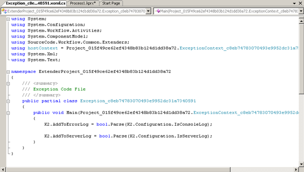
Insert the custom exception code within the file and save it.
The Process Start Rule can be accessed by clicking on the  icon in the Process Title Bar
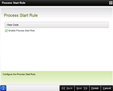
The Process Start Rule wizard allows the designer to insert custom code within the process Start Rule. The Start Rule determines the conditions under which the process will start. If the conditions are not met, the process will not start.
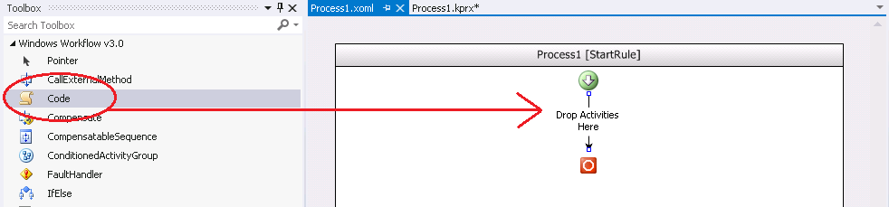
There are no advanced UI features and no default code. Viewing the code for the rule will present an empty XOML Windows Workflow Foundation design canvas, it is up to the designer to create the custom code. Use a Windows Workflow Foundation code activity by dragging it from the toolbox onto the Drop Activities Here area.
| Option | What it is | How to use it |
|---|---|---|
| Enable Process Start Rule | Enabling this option allows the process creator to add custom code to the Start Rule | Click on the check box, then click on View Code to load the XOML screen. Insert the required code within the process Start Rule (see below) |
The process Start Rule is not a required feature. If no process start rule is configured, no validation is performed once the process is started and the process will continue as if the rule evaluated to true.
Editing the Custom Code
Clicking on the View Code button from the process start rul wizard loads the Start Rule XOML file.
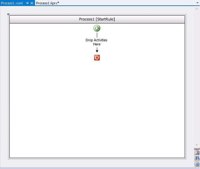
Insert the custom code within the file by dragging the Code Activity from the Windows Workflow Foundation toolbox and save it. Right click on the activity and select View Code to add the custom code.
Alternatively, right-click the Drop Activities Here section and select View Code to open the Start Rule class code file.
Insert the custom Start Rule code within the file and save it.
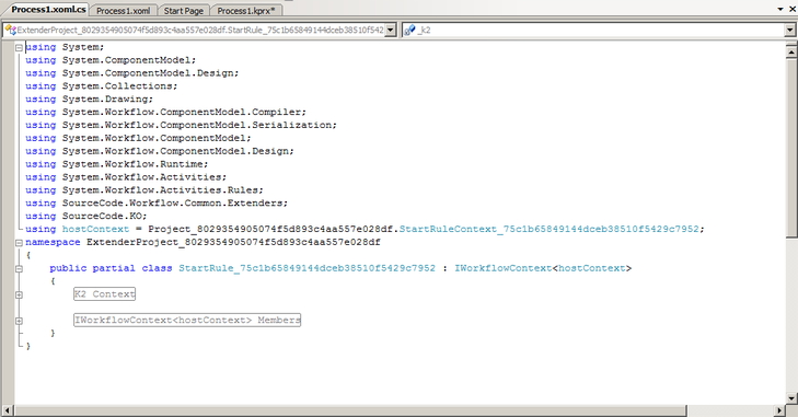
Example
In this example we used the code activity, then opened the code by double clicking on the code activity.
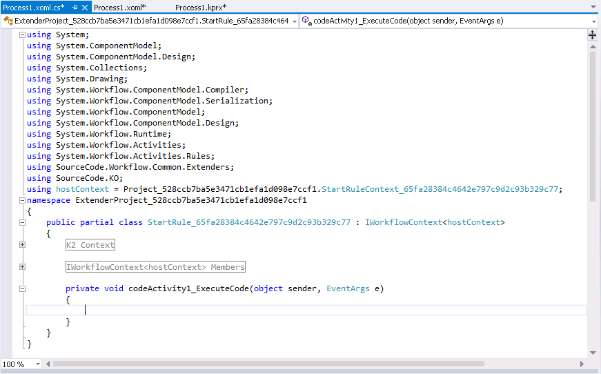
We then added the following code:
public partial class StartRule_56e27d9756b6483b839228b89c302d07 : IWorkflowContext<hostContext>
{
#region K2 Context
private hostContext _k2;
#endregion
#region IWorkflowContext<hostContext> Members
public Project_25f626e034434aa78505f21d614afb93.StartRuleContext_56e27d9756b6483b839228b89c302d07 K2
{
get
{
return _k2;
}
set
{
_k2 = value;
}
}
#endregion
private void codeActivity1_ExecuteCode(object sender, EventArgs e)
{
bool start = true;
//Check data field to determine whether or not the process should be started:
if (K2.ProcessInstance.DataFields["Some Field"].Value == "Sales")
{
start = false;
}
K2.Start = start;
}
}
}
In this example, the process will check for the Data Field "Some Field" and if the value is equal to "Sales", the process will be started. If the value of the Data Field is not equal to "Sales", the process will not be started. In addition, if the Data Field cannot be found, an error will be received.
For the Process Finish Rule to fire, it must be enabled at design time as the rule is not enabled by default. The Process Finish Rule wizard does not have any additional user configurable screens, other than the one shown below and configuration is via custom code additions only. The Finish rule executes as part of the process execution and is the last item executed just before the process completes. If an exception occurs as a result of the Finish Rule execution, the process will go into error.

How to use the Process Finish Rule
The finish rule can be used for house keeping, final notifications, etc. For house keeping requirements, the rule can delete a document library, temporary folders or send an E-mail.
The finish rule will execute last, just before the process completes.
What to do
To implement the finish rule, it has to be done in code as there is further access to a user interface beyond the initial screen where the rule is enabled. As shown in the image below, a code activity is added and your custom code is written.

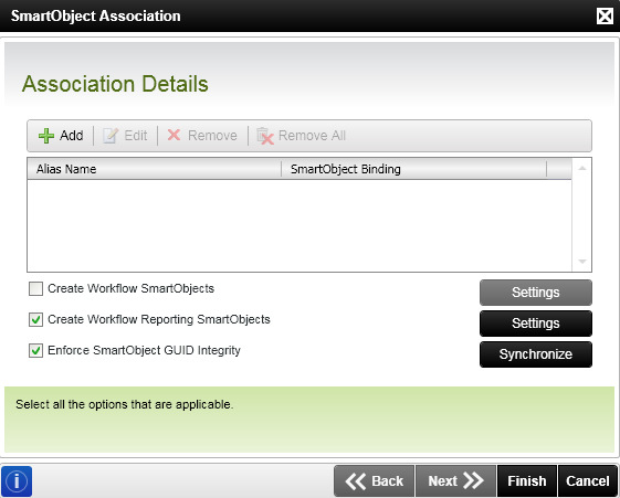
The SmartObject Association wizard creates a mapping between a process data field and a SmartObject property. The SmartObject Association wizard is accessed in the K2 blackpearl Object Browser > Process/Activity Data. To open the wizard right-click on the Associations folder and select the Add button.
| Feature | What it is | How to use it |
|---|---|---|
| Add | Opens the SmartObject Association wizard allowing the configuration of a new association. | Complete the SmartObject Association wizard screens to configure a new association. |
| Edit | Allows the existing associations to be modified. | Select the association to be modified and click Edit. The SmartObject Association Wizard with the association details will be opened. |
| Remove | Deletes one association at a time. | Select the association to be deleted and click Remove. |
| Remove All | Deletes all associations shown in the window. | To delete all the displayed associations click Remove All. |
| Create Workflow SmartObjects | Creates the workflow process as a SmartObject with SmartObject properties and methods. | Check the Create Workflow SmartObjects check box. Clicking the Settings button allows the user to select specific events in the process. |
| Create Workflow Reporting SmartObjects | Creates the workflow process as a SmartObject that is shown in the reporting components. | Check the Create Workflow Reporting SmartObjects check box. Clicking the Settings button allows the user to select specific events or activities in the process. |
| Enforce SmartObject GUID Integrity | Ensures that the SmartObject GUIDs and the SmartObject association mappings are synchronized when switching between environments. When the Ensure SmartObject GUID integrity check box is not selected the check to see if the GUIDs differ will be ignored and SmartObjects with new GUIDs will be created if they do not exist or the GUID from the Server will be used if it exists. | Check the Enforce SmartObject GUID Integrity check box and click the Synchronize button. |
| Synchronize | Defines the environment and SmartObject server that the current environment must be synchronized with. | Select the environment and SmartObject server that the current environment must be synchronized with. |
The Workflow SmartObjects and Create Workflow Reporting SmartObjects check boxes can be selected simultaneously ensuring that the process is created as a SmartObject; showing as a Reporting and a Workflow SmartObject.
Process references refer to external objects of components that a K2 process can access during deployment and runtime. By using the Process References dialog, you can access third-party and custom built objects, incorporating them within the workflow using the References Event wizard.
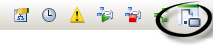
Click on the References button to open the Process References manager.
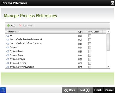
| Button | Description |
|---|---|
| Add | Opens the Add New Reference dialog, allowing you to add a third-party or custom reference to the K2 process |
| Remove | Removes the selected reference from the process |
| Remove All | Removes all the references from the K2 process |
| Copy Local |
Determines whether the reference is copied to the local output build path. If selected the assembly will then form part of the deployment package which is sent to the server.
At runtime the assembly will be copied to the working folder for the process and used from there. However, if the assembly exist in the GAC, the GAC version will be used instead. It is important to note that when it is selected a copy of that assembly will be deployed to the server each time a process is deployed that references that assembly. |
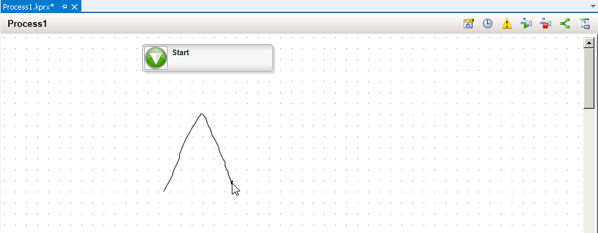
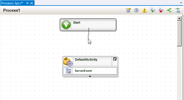
Mouse gestures speed up the design process when building a process. When working in the K2 Designer for Visual Studio, you can draw certain letters on the design canvas while holding down the right mouse button and the designer will place certain controls on the canvas relevant to the letter that was drawn.
For example, drawing an A on the canvas inserts an activity onto the process design canvas. Once an activity is on the canvas you can draw on the activity object itself to specify event types for that particular activity. For example, if you draw an M on the activity, an email event is added to the activity.
Below is a list of commonly used mouse gestures:
- A, O – Create a Default Activity on the canvas
- C – Create a Client event
- I – Create an IPC event
- M – Create an E-mail event
- S – Create a Server event with Code
- W – Create a Workflow Server event
- Right-click – Bring up context menu
- Drag – Move an activity by clicking on the icon (located in the upper left corner of the activity object)
- Double-click on Activity/Event Icon – Run the Property Wizard for selected object
- Double-click on Activity/Event Name – Start editing the name
- Double-click on Activity Description – Start editing the description
- Scroll Wheel – Scroll the canvas up and down
The following image demonstrates how a mouse gesture is drawn by creating an A on screen to insert an activity:
There are also some additional combination mouse and keyboard shortcuts available. Below is a partial list of some common combined items:
- CTRL + Drag-Select – Creates a bitmap of selected area and places on clipboard
- CTRL + Click-Select – Clicked-on object will be added/removed from selection (toggled)
- CTRL + Scroll Wheel – Zoom in and out
- CTRL + Mouse-Move – Holding the CTRL key down while moving the mouse over the Document View will show a preview of any bitmap that has been placed on the clipboard, as well as an insert location
- CTRL + Left-click – Holding the CTRL key down while clicking the left mouse button over the Document View will paste any bitmap that has been placed on the clipboard into the Document View at the indicated location
- SHIFT + Mouse-Move – Holding the SHIFT key while moving the mouse over the Document View will show an insert location for a new line of text
- Click + Mouse-Move – Holding the SHIFT key while clicking the mouse left button over the Document View will add a new line of text at the indicated position
- CTRL + Drag – (from the appropriate location on an activity) Draw a line
- SHIFT + Click – (on an IPC Event) Display a preview of the remote process
Visual Studio provides many hot keys by default and the K2 Designer takes advantage of this by extending and providing additional hot keys for working with common K2 tasks.
What are Hot Keys?
Hot keys you to work more quickly without having to leave the keyboard to utilize the mouse. Hot Keys provide quick access to common items needed when working within the development environment.
Using Hot Keys
To use a hot key, simply enter the required keystroke combination to complete the task. Many of the hot keys can be found by using the menu option with the mouse the first time, and taking note of the hot key that appears to the right of the text for the menu item. Additionally, the documentation can be useful for finding more hot keys.
Below is a list of Hot Keys within the K2 Designer for Visual Studio:
| Feature | What it is |
|---|---|
| CTRL + K, CTRL + 2 | Opens K2 Object Browser |
| CTRL + K, CTRL + E | Opens K2 Process Management |
| CTRL + C | Copy |
| CTRL + A | Select All |
| CTRL + V | Paste |
| F2 | Edit Activity/Event/Line Label/Name |
| ESC |
If editing a text object (like an Activity Name or Description), exits edit mode
If selecting, cancels the selection If dragging objects, cancels the drag If creating a new line, cancels the line If moving an existing line, disconnect it from the end activity and exit Line-Drag mode (causing the line to snap back to its start activity) |
| ALT + ENTER | Display the properties window |
| DELETE | Delete the selected objects |
Customizing Hot Keys
Hot keys can be customized in Visual Studio by opening the Tools > Options menu, choosing the Keyboard option and changing the default hot keys.
Many objects or controls on the design canvas can also be connected by simply drawing a free-hand line from one item to another. To draw a line, click and hold the right mouse button as you move the mouse from one activity to another.
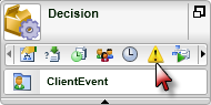
The color and icon of an activity can be customized to reflect the user's preferences. This can be done by right-clicking on the activity and selecting the option from the context menu.
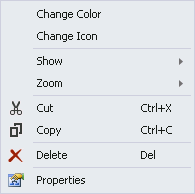
The following is a customization of a client activity:
.